|
|
|||||
| |||||
|
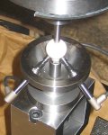
On five-axis machine tools, error motions of each linear/rotary axis, as well as its alignment (assembly) errors, are accumulated in the positioning error of a tool relative to a workpiece. No matter how small each axis' error motions are, assembly errors cannot be eliminated without spending much time and cost for post-assembly accuracy test and mechanical adjustment. For typical machine tools, the thermal deformation or the “aging” is one of the most critical error factors. It is particularly the case for five-axis machines. To maintain higher machining accuracy, thorough accuracy tests and adjustment/tuning before the shipping by a machine tool manufacture may not be sufficient – on-site error calibration and compensation by a machine tool user may be crucial. We have published a scheme to apply the "R-test" to the identification of geometric errors, or the "error map," of rotary axes in an efficient, automated manner. In this project, we have developed an R-test analysis software by integrating the proposed analysis schemes. The software, named "FKD system," is now commercially available from our research partner, Fukuda Corp. Major functionalities of the developed software are summarized as follows:
This work was done with Mr. Yu Nagai (March, 2015). >> Publications: CJ74, CE57, CE55, CJ73 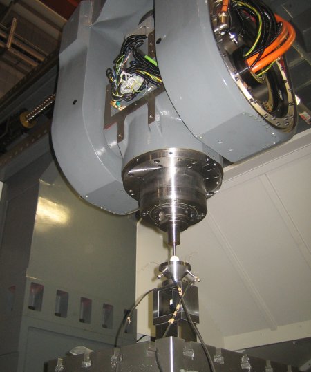
Figure 1: The software supports five-axis machines of various configurations. This photo shows the R-test setup for a five-axis machine with two rotary axes in the tool side (universal head). 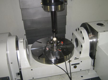 Figure 2: R-test setup for a five-axis machine with a tilting rotary table. 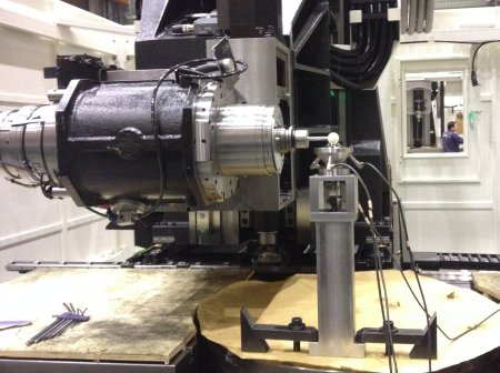 Figure 3: R-test setup for a five-axis machine with a rotary table and a tilting head. 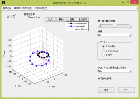 Figure 4: A screen-shot of the developed software "FKD system." 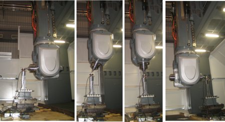 Figure 5: Test procedure for a rotary axis in the tool side (for the machine in Fig. 1). 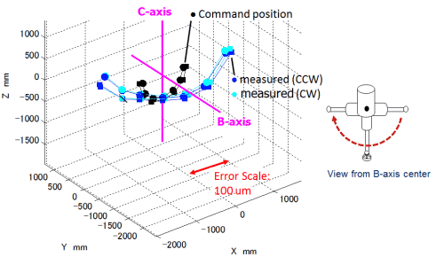
Figure 6: An example R-test profile. On a five-axis machine with two rotary axes in the tool side (see Fig.1), the measured trajectory of the sphere center, attached to the machine's spindle, is shown. The sphere's command positions are shown in black dots. Their actual positions, measured by the R-test, are shown in blue dots. An error from the command sphere trajectory and measured trajectories is magnified 10,000 times. 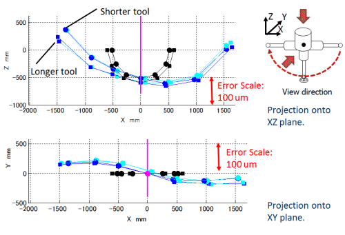
Figure 7: Projection of Fig. 6 onto the XZ plane (upper) and the XY plane (lower). Such a graphical presentation of R-test results helps us to make many intuitive observations of error motions of rotary axes. For example, in the upper plot, larger positioning error, larger than 100 um, can be observed at B=+-90 deg. This is mostly caused by the angular positioning error of B-axis at B=+-90 deg, combined with the miscalibration of the B-axis position. In the lower plot, the axial error motion of B-axis is clearly observed. 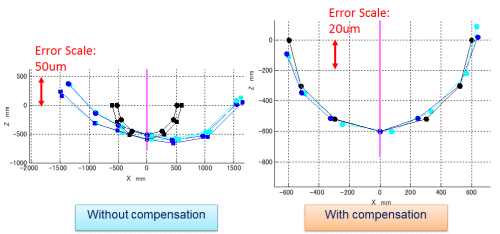
Figure 8: Measured sphere trajectories with and without numerical compensation of rotary axis error motions. Projection onto the XZ plane (see Fig. 7). The sphere's position error is reduced to 10 um at maximum by the numerical compensation.
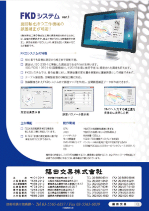
Figure 9: Package of the software "FKD system" commercially available from Fukuda Corp. | |||||
