|
|
|||||
| |||||
|
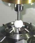
For example, suppose that the R-test device is installed on a rotary table (C-axis). Rotate the table and measure the relative displacement of the spindle-side sphere by the R-test. When there exists no error motion, the measured trajectory of sphere should be a perfect circle. The R-test calibrates error motions of the rotary axis by observing an error in the measured sphere trajectory to the command trajectory. Not only the angular positioning error of the rotary axis, but also various error motions such as squareness to linear axes, center shift, run-out, and tilt error motions, can be observed. When a rotary table (C-axis) is mounted on a swiveling axis (B-axis), error motions of C-axis often vary due to e.g. gravity-induced deformation, when the angular position of B-axis gets closer to vertical. An important advantage of R-test is in its efficiency to perform many measurements at various B- and C- angles. The measurement cycle can be automated. We have developed an intuitive, graphical presentation method of R-test measurements to understand error motions of rotary table in three-dimensional space, and how they change with the rotation of the swiveling axis (see Figs. 1 to 3). The "error map" of rotary axes can be numerically calibrated from R-test results. Its numerical compensation has been also studied. Furthermore, its application to a new thermal test for five-axis machining centers was proposed. The R-test observes how error motions of rotary axes change due to thermal influence. (April, 2012) >> Publications: JE26, JE25, JE23, JE19, CE47, CE44 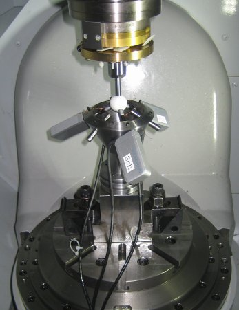 Figure 1: Our prototype R-test device. 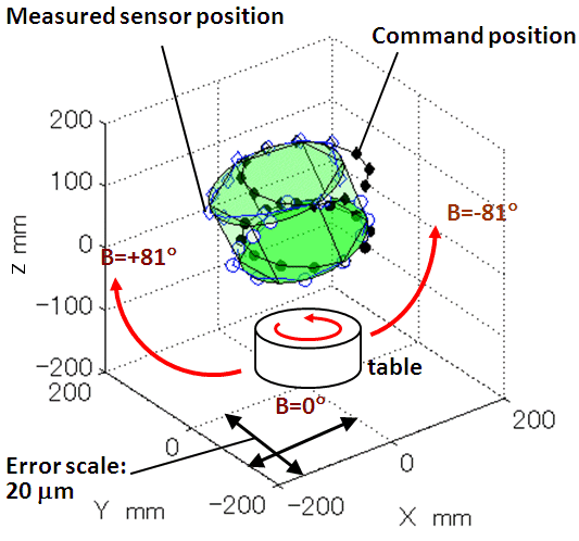
Figure 2: An example R-test measured profile, showing how the rotary table (See Fig.1) rotates at B=0 deg. Black dots represent the sphere's command position, and blue circles show its actual position measured by the R-test. The error is magnified. Circles painted in green represent an average circle calculated from measured sphere positions.
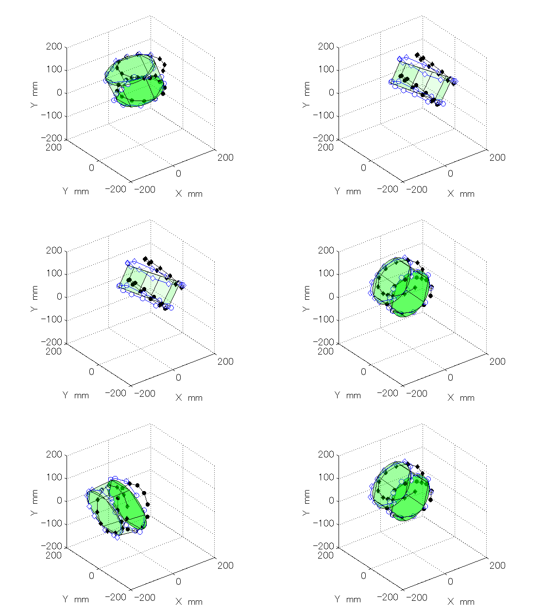
Figure 3: The R-test measurement shown in Fig. 2 was performed at various B angles. This animation enables us to visually understand how error motions of the rotary table (C-axis) vary with the rotation of the swiveling axis (B-axis). The "error map" can be numerically constructed from this.
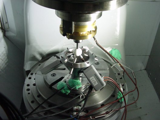
Figure 4: Thermal test by R-test. 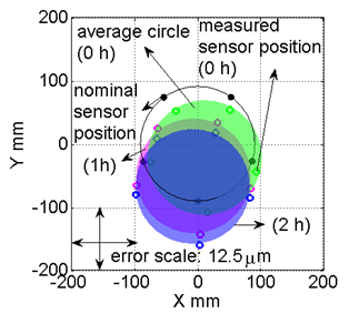 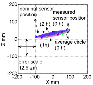
Figure 5: An example of the thermal R-test result. The proposed thermal test observes how heat generation by reciprocating motion of a swiveling axis influences error motions of a rotary table. These plots show measured sphere trajectories at B=0 deg by the R-test (upper: projection onto XY plane, lower: projection onto ZX plane). By repeating reciprocating motion for 0, 1 and 2 hours, the center of the rotary table (C-axis) moved mainly to -Y direction. | |||||
