|
|
|||||
| |||||
|
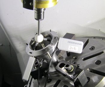
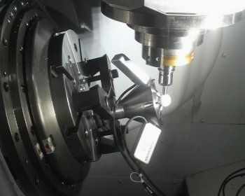
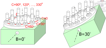
The R-test device consists of a precision sphere attached to the machine's spindle and three linear displacement sensors installed on the table. Each sensor is directed approximately to the sphere's center. By the kinematic computation, sensors displacements can be transformed into the three-dimensional displacement of the sphere center. Its measuring principle, the measurement of sphere center using a linear displacement sensor, is common with many conventional measuring devices such as the ball bar measurement. While the ball bar measurement is one-dimensional, the R-test collects a three-dimensional error trajectory in an automated measurement cycle, requiring no setup change. The R-test has a strong potential advantage for efficient and automated error calibration. In our R-test procedure, two rotary axes are indexed at various angular positions. where the three-dimensional displacement of the spindle to the work table is measured by the R-test. We proposed an algorithm to construct an "error map" of rotary axes by analyzing a set of collected displacement data. In addition to fundamental location errors of rotary axes (e.g. center offset or orientation error of axis average line), our algorithm quantifies more complex error motions, such as linear or tilt error motions of rotary axes, or their variation caused by the gravity-induced deformation. (February, 2011) >> Publications: JE19, CE44, CJ53, CJ46, CJ45  
Figure 1: The prototype R-test device that we made. 
Figure 2: The R-test measurement sequence we presented. At various angular positions of two rotary axes, the three-dimensional displacement of the spindle to the work table is measured by the R-test. | |||||
