|
|
|||||
| |||||
|
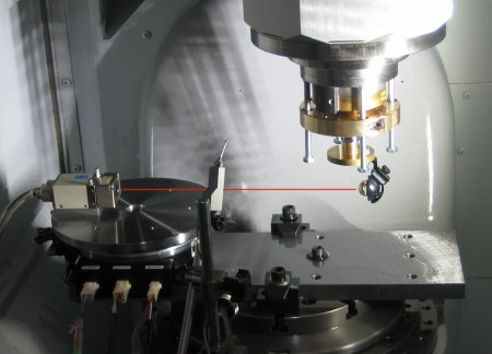
In the multi-lateration (trilateration) principle, the target retroreflector's position is estimated by the distances from the tracker to the target; the direction of laser beam is not included in the multi-lateration calculation (unlike the triangulation). Therefore, in principle, the accuracy in laser beam direction control does not influence the measurement uncertainty. According to this characteristics, high-accurate automated tracking of target retroreflector is not essential in the multi-lateration measurement. The command position of target retroreflector is given in priori. By simply regulating the laser beam toward the command target position, essentially the same multi-lateration measurement should be possible without the automated tracking mechanism -- this is the basic idea of this project. In other words, just by mounting a laser interferometer on a rotary actuator, the same measurement can be done as the automated laser tracker. In this project, this measuring instrument is called the "open-loop" laser tracker -- 'open loop' in the sense that the target's actual position is not fed back to the control of laser direction. As a first step, to simplify the problem, this project focused the two-dimensional measurement of target position. A 2D "open-loop" laser tracker prototype was developed, mounting a laser interferometer on a single-axis rotary table. The uncertainty in the measurement of 2D position trajectory of a machining center was investigated both by experiments and uncertainty analysis. (March, 2011) >> Publications: JE30, CJ67  Figure 1: Experimentation with the 2D "open-loop" laser tracker prototype. The laser beam direction is regulated by a rotary table. The test objective is to measure the 2D position of the cat's eye retroreflector attached to the machine spindle. The cat's eye retroreflector reflects the beam to the incoming direction. 
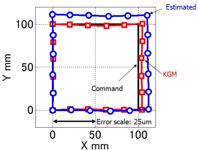
Figure 2: Two-dimensional position error trajectory estimated by using the "open-loop" laser tracker ("estimated"), as the machine tool is positioned at command positions along a 100mm*100mm square path. An error from the command position is magnified and plotted here. For the comparison, the 2D positioning error at same command positions is measured by a cross grid encoder ("KGM"). The difference of estimated and KGM measured trajectories is up to several micrometers, but it is mostly attributable to the machine's thermal deformation. | |||||
