|
|
|||||
| |||||
|
Thermal deformation is among major causes of machining inaccuracy on five-axis machine tools -- as many machine tool users empirically know. Even under a relatively simple thermal deformation, e.g. thermal expansion of spindle to Z-direction, it changes the rotary axis centerline position with respect to to the machine coordinate system, which could cause larger and more complex geometric errors of the machined workpiece. We proposed a machining test such that error motions of rotary axes can be calibrated by measuring the geometric accuracy of the machined test piece. By comparing error motions identified in prior to the machining, with those identified from the machined test piece, we can observe how the heat induced by spindle rotation influences error motions of rotary axes. Furthermore, by repeating the proposed machining test on multiple test pieces, the thermal stability of the motion of rotary axes can be evaluated (April, 2013) >> Publications: JE32, CE54, CJ68, CJ63 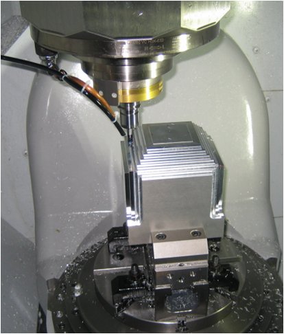 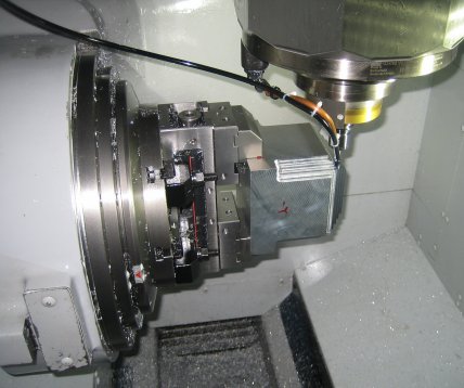 Figure 1: Machining test setup. 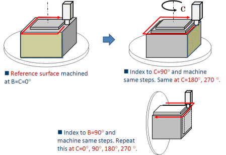
Figure 2: Machining test procedure. At various angular positions of two rotary axes, a square-shaped step is machined by a straight end mill. 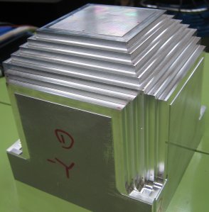
Figure 3: Machined test piece. 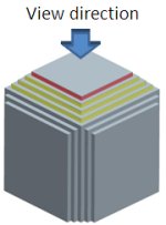
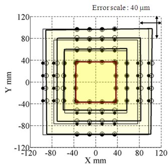
Figure 4: Geometric errors of the machined test piece, measured on-machine by using a touch-triggered probe. Four square-shaped steps are machined at C=0, 90, 180 and 270 deg and B=0 deg. White circles represent the measured positions, and black circles represent their nominal positions. The error between them are magnified. It can be observed that the position or the size of each square-shaped step has an error about 5 to 10 um. Its major cause is the position error of C-axis centerline. 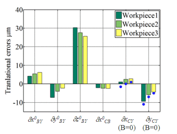
Figure 5: Geometric error parameters of the machine's rotary axes, identified by measuring the geometric accuracy of the machined test piece. The present parameters represent position errors of C- or B-axis centerline. By repeating the proposed machining test three times, the change in identified error parameters is investigated. The thermal deformation of machine structure, induced mainly by spindle rotation, moves B- and C-axis centerlines with respect to the machine coordinate system. | |||||
