|
|
|||||
| |||||
|
As an extension of the diagonal measurement, the step diagonal measurement has been recently proposed. As shown in Fig.1, in the step diagonal measurement, each axis is moved one at a time along the "zig-zag" path toward the body diagonal direction. A strong advantage of the step diagonal measurement is that it can separately identify positioning errors, straightness errors, and squareness errors of all of X, Y and Z axes. Typically, straightness and squareness errors are measured by using a high-precision displacement sensor and an artifact such as a straight edge or a squareedge (see Fig. 2). For orthogonal three-axis machines, 3 linear displacement errors, 6 straightness errors and 3 squareness errors must be measured by different setups. Especially when the measurement range is larger, a long artefact is needed, which requires higher measurement cost. The laser step diagonal measurement can evaluate all the errors by using a laser interferometer only. However, when the conventional formulation of step diagonal measurement is used, it was reported that there were cases where the estimates by the step diagonal measurement show a significant error from the measured values by using an artefact. This project first discusses inherent issues with the conventional formulation of step diagonal measurement, in order to clarify this reason. Then, we proposed a new formulation of step diagonal measurement such that this issue can be cleared. The effectiveness of the laser step diagonal measurement was experimentally verified. (March 2008) >> Publications: JE16, JE10, CJ40, CE38, CE32, CJ38 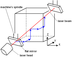
Figure 1: An overview of laser step diagonal measurement. The laser direction is fixed to the body diagonal direction. The machine moves along the zig-zag path toward this diagonal direction. Its diagonal displacement is measured. 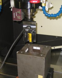
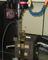
Figure 2: A typical setup to measure straightness or squareness errors. A squareedge or a straightedge and a displacement sensor are used. For orthogonal three-axis machines, 3 linear displacement errors, 6 straightness errors and 3 squareness errors must be measured by different setups. 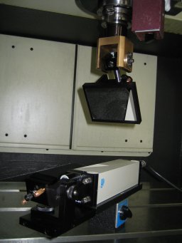
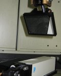
Figure 3: The setup of laser step diagonal measurement. A wide mirror is used as the target, such that the laser can return when the target moves along the zig-zag path. In the experiments, we used a laser doppler displacement sensor by Optodyne, Inc. | |||||
