|
|
|||||
| |||||
|
Contour parallel paths, which are given by simply offsetting the product geometry to be machined, inevitably causes the variation of cutting forces, which may result in a severe tool damage especially in the machining hardened materials. Furthermore, since such a variation in cutting forces naturally causes a variation in the tool deflection, it likely causes the variation in the geometric error of the machined surface. In this project, we proposed a new tool path generation scheme to avoid this issue with contour parallel paths. The tool path is slightly modified from original contour parallel tool paths such that the variation in cutting forces under the finishing path can be avoided as much as possible, and the finishing path can be machined under approximately constant cutting force. Since the proposed scheme only modifies the single semi-finishing path, it does not require much computational loads. By applying the modified path, it was experimentally verified that the geometric error of the machined surface was significantly reduced, even though exactly the same machine tool, the same tool, the same machining conditions were used. (September 2007) >> Publications: JE8, JE6, CE31, CE29, CE21, CJ18 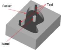
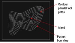 Figure 1: A simple example of contour parallel tool paths. To machine the pocket shown left, contour parallel tool paths in the right figure can be used. These paths are generated by simply offsetting the pocket geometry to be machined. 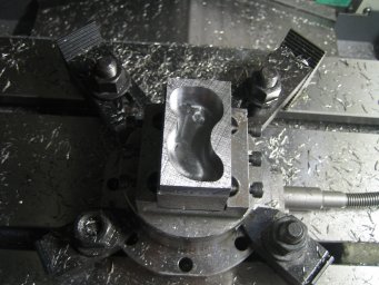 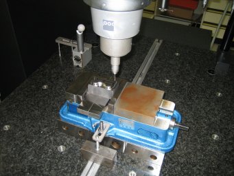 Figure 2: A machining experiment. The above shows the test piece machined on our machining center. In the photo below, the geometric accuracy of the machined pocket contour is measured by using a coordinate measuring machine (CMM). 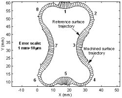
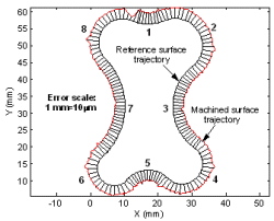 Figure 3: An example of experimental results. The geometric error of the machined pocket contour is magnified and plotted. The left one shows the profile when the pocket is machined by using the original contour parallel tool path. It can be observed the error significantly varies depending on the geometry of the contour. This is caused by the variation in cutting forces on the finishing path. The right one shows the profile when the modified tool path was used. The error becomes approximately uniform. The machine tool, the tool, machining conditions were exactly the same in both machining tests. | |||||
