|
|
|||||
| |||||
|
On the other hand, it is often subject to higher frequency "noise"-like measurement errors. Its amplitude is dependent on the target surface material or quality. In an example shown in Fig. 1, the amplitude of "noise" is up to 20 um. This measurement error's repeatability is high, and is thus not a random "noise." First, in this project, we developed a model to clarify that the speckle noise in laser beam reflection causes this "noise"-like measurement error. Figure 2 shows the speckle noise in the reflected image of laser beam measured by using a 2D CCD sensor array. Figure 2 shows the speckle's movement as the sensor moves in the direction parallel to the target surface. This movement is "misunderstood" as the change in the distance to the target. Then, we tested a scheme to reduce the influence of speckle noise by using two CCD sensors aligned symmetrically around the laser beam axis. Preliminary tests were conducted by using two commercial laser displacement sensors (see Fig. 3). To further investigate its effectiveness, as well as its limitation, experiments were done by using two 2D CCD cameras (see Fig. 4). This work was done with Mr. Yoshitomo Kitagawa (March, 2015). 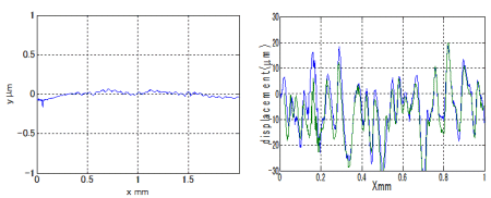
Figure 1: Comparison of measured profiles by a stylus-type surface roughness measurement machine (left) and a triangulation-based laser displacement sensor (right). A steel block gauge (Ra<0.01 um) was measured. In the measured profile by a laser displacement sensor, the variation up to +- 20 um can be observed. This is this sensor's measurement error. The blue and green lines represent two repeated tests. The repeatability is high. 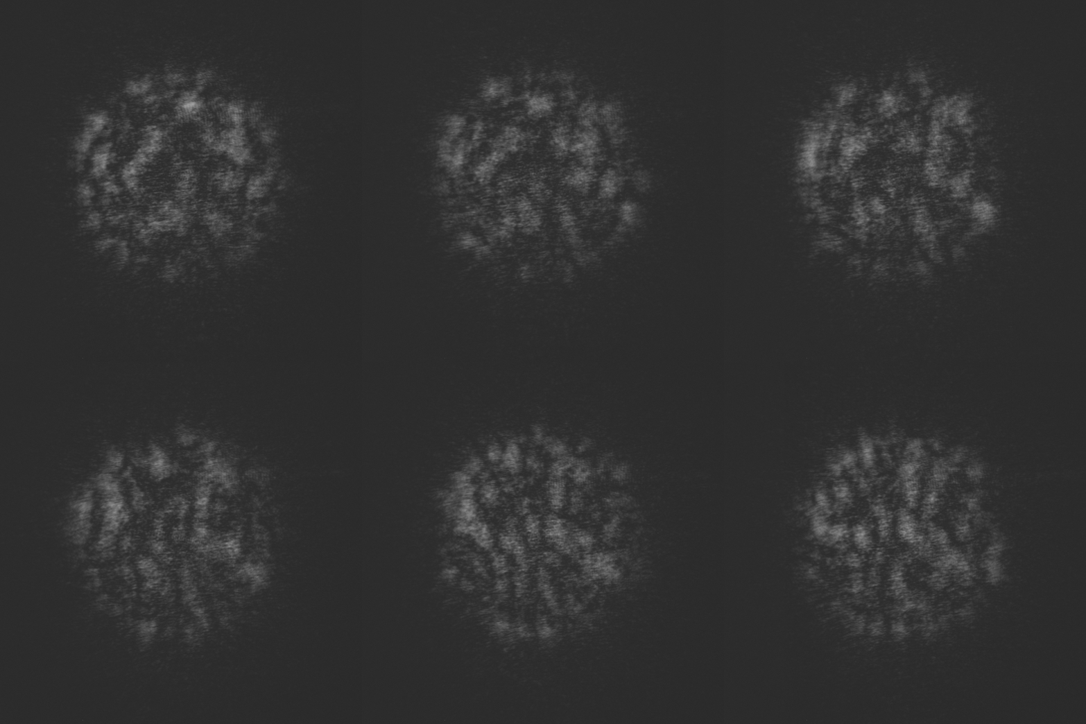
Figure 2: An example speckle noise measured by using a CCD camera in the setup shown in Fig. 4. The speckle's movement is shown as the sensor moves in the direction parallel to the target surface. This movement is "misunderstood" as the change in the distance to the target. 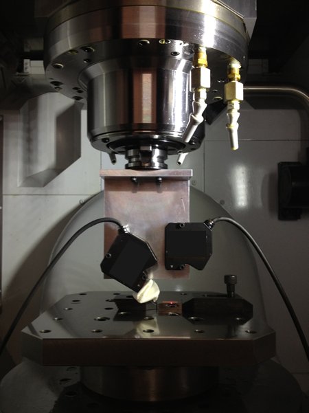
Figure 3: By using two CCD sensors aligned symmetrically around the laser beam axis, the influence of speckle noise can be reduced. In this experiment, two commercial laser displacement sensors are attached to a machine tool's spindle. 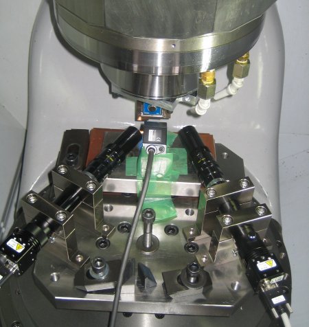
Figure 4: To further investigate the proposed scheme's effectiveness, as well as its limitation, experiments were done by using two 2D CCD cameras. Here the target block gauge is attached to the machine spindle, and two cameras are fixed on the machine table. | |||||
