|
|
|||||
| |||||
|
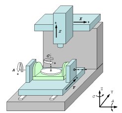
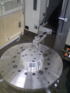
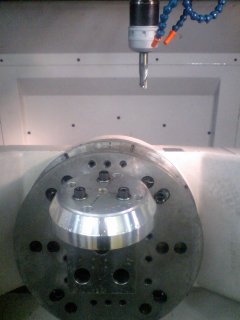
In the machining by using a 5-axis machine tool, various error sources in each of rotary and linear axes impose complex effect on the geometric accuracy of the machined workpiece. In this project, we have developed a machining simulator of the 5-axis machining in order to separately analyze the effect of each error source on the machining accuracy. As an application example of practical interest, the error simulation of the machining of a cone frustum, as is described in the NAS979 standard, is analyzed in details. The tilt errors of the center axis of rotary axes (e.g. the squareness between a rotary axis and the X or Y axis) or its traverse errors are collectively called kinematic errors. They are clearly one of the most fundamental error sources caused by the assembly of each axis. When kinematic errors are identified in advance, and the effect of each kinematic error on the machining accuracy is evaluated, it is possible to compensate them by the modification of commanded positions. In this study, compensation experiments were also conducted, verifying that the roundness error of the machined cone frustum was significantly reduced by applying this compensation. (September 2007) >> Publications: JE18, CE41 JE11, CE34 
Figure 1: A typical configuration of 5-axis machine tools. This configuration has a rotary table to rotate a workpiece, and a rotary axis to tilt the table.   Figure 2: A test piece machined by the cone frustum machining test. The left photo shows the measurement of its roundness error profile by using a roundness measurement machine. The right photo shows the workpiece set on the 5-axis machine. | |||||
