Volumetric accuracy of machine tools
-- Kinematic modelling, measurement and compensation of 3D motion errors --
Professor, Hiroshima University
Soichi Ibaraki, Ph.D.
Morikita Publishing Co., Ltd.
Price: \3,780
ISBN:978-4-627-62511-2
Year: 2017.04
Buy on-line at Morikita Publishing's page.

Also available from other on-line book stores, e.g. Amazon. Links are in Morikita Publishing's page.

(From Morikita Publishing's site)
Market demands for higher accuracies of machine tools has been increasing. The assessment of the volumetric accuracy of a machine tool requires direct measurement of three-dimensional trajectory of a tool center point. This is a new concept for machine tool accuracy metrology. This concept is introduced in some latest ISO standards related to machine tool accuracy testing, and the corresponding JIS standards will be also available. This book introduces the theory of machine kinematic modelling, and its application to the volumetric accuracy measurement for 3-axis and 5-axis machine tools, with many practical application examples. The author has been deeply involved in the development of ISO and JIS standards related to machine tool accuracy testing. The book is a good text book for engineers, researchers, and students studying machine tools.
The book is in Japanese.
The following Qs and As overview the book:

What is the volumetric accuracy of a machine tool? For what machines should we assess it?

As an example, consider the X-axis linear positioning error on a large-sized machine tool illustrated below. In typical accuracy inspection by a machine tool builder, only one line is measured. On such a large-sized machine tool, is the X-axis linear positioning error always the same for any Y positions?
From my experiences, the X-axis linear positioning error can significantly vary at different Y positions. For the machine configuration above, typical causes include the angular error motion (pitch error motion) of the X-axis.
The plot below shows this machine's "error map" on the XY plane. This enables us to assess the machine's 3D positioning error in the entire 3D workspace. Such an assessment is called the assessment of the volumetric accuracy.
Suppose that we measured all the error motions, i.e. the linear positioning error motion, the straightness error motion, and angular error motions, of X-, Y-, and Z-axes. How do we compensate for the volumetric error?
An arbitrary command position (x,y,z) should be compensated for by the following equations. When the function "3D Rotation Error Compensation" in Fanuc CNC controllers is used, the compensation table can be straightforwardly generated by using the following equations.
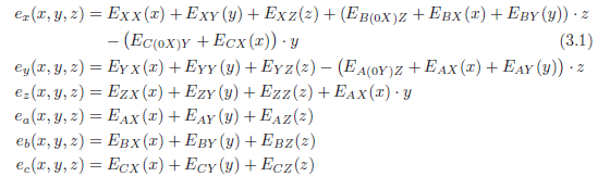
The notation of the symbols is explained in the book. Different equations are needed for different machine configurations. The book illustrates the theory of the coordinate transformation to derive this kinematic model of a machine tool of arbitrary axis configuration.
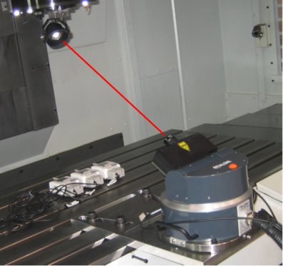
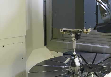
What is the laser tracker, and what we can measure by it?
The laser tracker is a laser interferometer with an automated tracking mechanism to regulate the laser beam direction to a target retroreflector. The photo below shows the LaserTRACER by Etalon.
The multilateration algorithm to measure the machine tool volumetric accuracy is available. It can estimate all the error motions, i.e. the linear positioning error motion, the straightness error motion, and angular error motions, of X-, Y-, and Z-axes, by solving the following minimization problem:
The kinematic modelling is deeply associated with this algorithm. The book explains it in details.
How do we estimate error causes from the workpiece's geometric error finished by a five-axis machine tool? We need partially-automated error cause diagnosis.
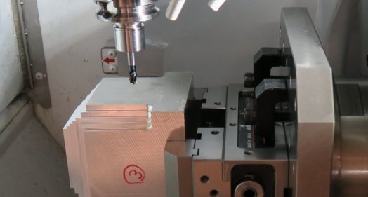
You need the kinematic model. When there exist position and orientation errors of rotary axes, the trajectory of tool center point, which will be copied as the finished workpiece's geometry, will be given by:
The notation of the symbols is explained in the book. The book illustrates this kinematic modelling for five-axis machine tools of arbitrary axis configuration. By inversely using this model, rotary axis error motions can be identified from the finished workpiece's geometry.
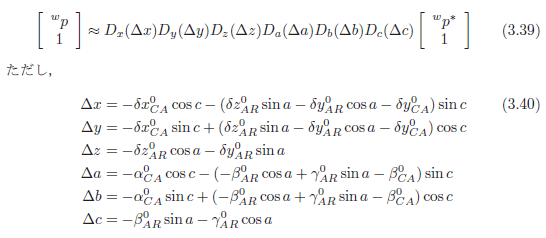
What is the R-test, and what we can measure by it?
The R-test instrument measures the 3D displacement of a sphere, attached to a machine spindle, by using three contact-type linear displacement sensors.
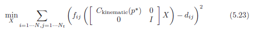
By using the five-axis kinematic model, position and orientation errors of rotary axes can be identified from the spherefs 3D displacement by the R-test. This comes down to the following minimization problem:
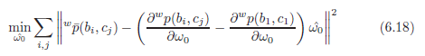
The book explains the R-test analysis algorithm in details.
|