|
|
||
|
||
|
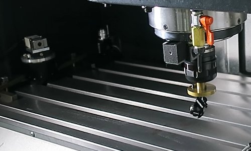
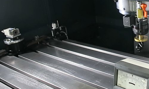
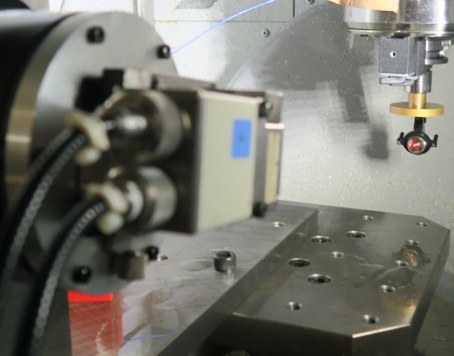
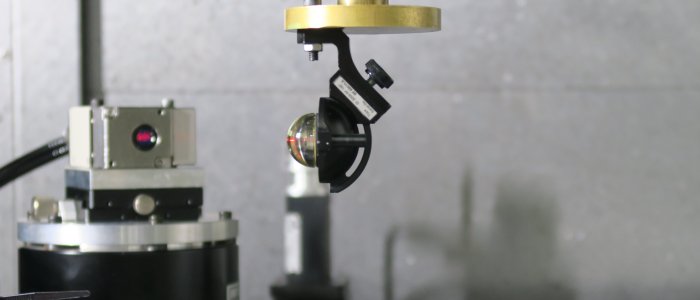
"Open-loop" laser tracker prototype When machine toil builders measure the motion accuracy of linear axes, each error motion of each of X, Y and Z axes is independently measured by using a different measuring instrument and a different setup. For example, the linear positioning deviation is measured by a laser interferometer. The straightness deviation is measured by using e.g. a straight edge and a dial gauge. Angular error motions are measured by using e.g. an autocollimator or a precision level. The squareness error between two linear axes should be measured by using a square. To significantly reduce time and cost with such measurements, we proposed a new scheme to measure all these error motions by using a laser interferometer only. A laser interferometer is typically used to measure the distance when the laser beam is aligned to the direction of the machine's movement. In our scheme, the laser beam direction is regulated to follow the machine, which moves along an arbitrary 2D path.
The proposed scheme is close to the multilateration measurement by a laser tracker. While a commercial laser tracker has an automated tracking mechanism and is very expensive, our scheme only requires a laser interferometer mounted on a rotary table. In this project, a prototype instrument was developed with a rotary table driven by a PLC controller, and several experimental case studies were conducted. >> Publications: JE12, CJ18, CJ4 |
||